Welcome to our community

Be a part of something great, join today!

  • Hey all, just changed over the backend after 15 years I figured time to give it a bit of an update, its probably gonna be a bit weird for most of you and i am sure there is a few bugs to work out but it should kinda work the same as before... hopefully :)

Wiring a battery plate (HELP)

Chris Elkerton

Well-known member
Joined
Nov 14, 2012
Messages
157
Reaction score
0
Points
16
Location
UK
Website
www.chriselkerton.com
Hi,
I'm looking for a bit of help. I am looking to build a DIY battery plate for my Red One. I have a Farseeing battery plate and a Lemo powered cable which I have cut in half.
My question is how do I know which wire is which in the lemo cable? I have read the thread on here with someone trying to do pretty much the same thing, the advice is great but it doesn't really cover this.
I have included this photo hoping that someone can identify the wires by the colours. Any advice is welcome, thanks.
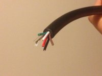
 

Attachments

  • image.jpg
    image.jpg
    107.5 KB · Views: 0
Page 138 of the Red One Operation Guide - DC Power Input pinout of the Red One viewed into the camera connector. You need a continuity meter to work out which colour wire corresponds with which pin in your cable.

It's vital that TWO pairs of power pins in the 6-pin Lemo connector are all correctly wired to the battery plate positive and negative pins. Failure to do so will damage a circuit board in the camera which will be an expensive repair - the damage can apparently be subtle and may not present itself as a dead camera initially.

If in doubt, get a competent technician to do it for you, rather than risk frying your camera.
 
Note that your cable only has 4 cores, so you won't be able to connect the battery data pins.
 
Foolproofest way: Strip the wires on the end still attached to the plate, and pop a battery on. Measure the power coming out of each color wire and just write down what they are. You avoid having to probe the tiny Lemo conductors then.
 
Hi,
thanks for the replies.
I have now identified the wires in the cable using a multimeter.
I am now looking at wiring up the plate. My question is; is there any reason why I can't solder the two (+) wires to the (+) coming out of the battery plate? And then likewise with the two earths? Sorry if this sounds stupid, but I just want to make sure.
 
Hi Chris

It doesn't sound like you've done much electrical work before, so your caution is sensible.

Of course you are proceeding at your own risk, as any instructions you are given from a written forum can only do so much.
As said already, if in doubt find a competent friend or technician to do it for you.

If you still want to proceed, then once you're done soldering, double check everything before finally connecting a battery and connecting to your camera.

Remember the Pin-out diagram in the Red One Operation Guide on Page 138 is viewing from outside the camera looking into the power connector on the camera.
So looking at the pins of your cable from outside the cable connector the pin numbers will be a mirror image.
https://www.red.com/downloads/4f56854d6261f95a57000647

Having said all that, if you have correctly identified the two positive and two negative wires in the cable, then yes you can solder both positive (+) wires to the (+) from the battery plate contacts. And likewise with both the negative (-) earths.

You can double check which of the battery plate contacts is positive and which is negative by putting a battery on the plate and measuring the volts on the soldering side of the plate.
 
Hi Eric,

thanks for the reply, I appreciate your advice.
Yes, I understand what you are saying and on your previous advice spoke to an electrician friend of mine. For anyone who wants to know, this is what I did. I offered the lemo cable up the the DC input on the camera, then as Eric mentions above, using the diagram in the user manual I labeled the corresponding pins on the cable using masking tape and a pen (then checked and triple checked it!!). I then used a multimeter to see which pin was connected to which wire by putting a probe on the pin and then checking the wires one by one with the other probe.The multimeter was set to bleep when it made a circuit (my electrician friend talked me through this, I have no idea how to use a Multimeter!) I then checked and checked again. I also checked the (+) and (-) on the battery plate by putting a battery on it and testing the voltage coming through.
I just wanted to check it was okay the solder the wires directly to the plate wires, rather than using terminal blocks. I will probably test the wires again once the cable is wired up, before I connect to the camera.
 
Well, looking at the website for your battery plate, it looks like they provide pre-soldered wires with premade connectors and red and black wires indicating the positive and negative wires respectively.

Yes, you could remove the existing connector and solder directly to the plate wires - just make sure to insulate the joints with electricians PVC insulating tape, or better use some silicone insulating sleeves or heatshrink sleeves (available from www.maplin.co.uk stores).

If you ever intend to use the P-Tap connector on the side for powering accessories, note that the D shape of the connector is intended to prevent P-Tap connectors being inserted the wrong way up and prevent reverse polarity power going to your accessories. The D shape is a poor key, so it's often possible to force P-Tap connectors onto it the wrong way with little effort. So be careful to visually check when using it.
 
That diagram on p 138 is not really very clear. It looks like they suggest bridging 4 of the pins together (MAKE SURE THAT'S CORRECT BEFORE YOU SOLDER>> I DONT KNOW IF I AM UNDERSTANDING IT PROPERLY) Anyone willing to post a photo of the inside of the lemo showing what's going on in there?
 
That diagram on p 138 is not really very clear. It looks like they suggest bridging 4 of the pins together (MAKE SURE THAT'S CORRECT BEFORE YOU SOLDER>> I DONT KNOW IF I AM UNDERSTANDING IT PROPERLY) Anyone willing to post a photo of the inside of the lemo showing what's going on in there?

Bridging the correct pairs of pins in the Lemo would also work. Arguably that would also protect somewhat against a power wire going open circuit and no longer supplying power to two pairs of pins for the camera.
 
Bridging the correct pairs of pins in the Lemo would also work. Arguably that would also protect somewhat against a power wire going open circuit and no longer supplying power to two pairs of pins for the camera.

What do you mean by bridging Eric? Am I right in thinking this would mean soldering the two (+) wires to the one (+) from the plate?
 
That diagram on p 138 is not really very clear. It looks like they suggest bridging 4 of the pins together (MAKE SURE THAT'S CORRECT BEFORE YOU SOLDER>> I DONT KNOW IF I AM UNDERSTANDING IT PROPERLY) Anyone willing to post a photo of the inside of the lemo showing what's going on in there?

Thanks for posting Christopher. I am not 100% sure I understand. The diagram shows (or at least as i understand it) that the two (+) wires in the lemo need a (+) from the battery. Then likewise with the earth wires. The only way I can think of doing this would be to solder the two wires to the one. What are your thoughts on this?
Also, do the mean a photo of the inside of a lemo cable? Or are you referring the the DC connector on the camera?
Thanks,
Chris.
 
I am saying that I don't understand it either. I was going to shorten a regular R! power cable and wire the cables to an AB Gold mount plate I have on hand, but realize I cant understand which wires to solder where.. The diagram is not undertandable by me.
 
Chris

Don't let Christopher Mills' post confuse you. What you were going to do based on original posts is fine.

Bridging in this case just means soldering a wire between the two positive pins, and A SEPARATE wire between the two negative pins. This would serve the same function of making sure the camera had two pairs of positive and negative power, and even if one of the wires went open circuit it would still have both pairs of power connections. But you'd have to open up the Lemo, unsleeve and unsolder the existing connections and get into soldering some fiddly pins and resleeving instead of the simple cable joints.

However, as long as you look after your cable and don't use it if it gets damaged until it's repaired, this is generally unnecessary. Certainly Red's own battery plates don't bother bridging pins.
 
I am saying that I don't understand it either. I was going to shorten a regular R! power cable and wire the cables to an AB Gold mount plate I have on hand, but realize I cant understand which wires to solder where.. The diagram is not undertandable by me.

Yes, you could bridge the pins as I explained above, and if your power cable only had one positive and one negative wire, then that would be what you had to do.

However, in this case the cable has four separate wires, each going to separate pins. So bridging pins is unnecessary.

If you can't follow the diagram (which is a standard electrical connector diagram). I would strongly recommend you find a electrically competent friend or technician to do it for you, or you risk frying your expensive camera with an expensive power board repair bill.
 
When you have finished soldering on the plate, please check the continuity again with the multimeter to make sure that the power terminals on the plate are sending power into all of the pins that need it.

It's better to be safe than sorry.

Freya
 
When you have finished soldering on the plate, please check the continuity again with the multimeter to make sure that the power terminals on the plate are sending power into all of the pins that need it.

It's better to be safe than sorry.

Freya

Hi Freya,
yes this sounds like good advice. Thanks.
 
Back
Top