- Banned
- #1
Guy Bryan Holt
Banned
- Joined
- Sep 20, 2009
- Messages
- 149
- Reaction score
- 0
- Points
- 0
Hi all. . .
I just purchased a 6K HMI. It operates at 220V, and it comes with a Bates connector…. it seems to me that a 6K, at 6000 watts, should be able to be run off your typical dryer outlet (which, in these parts are composed of two 30 amp 110 volt circuits) since 6000 watts divided by 220 volts equals just over 27 amps ...
the answer, as is often the case, is "yes" and "no" there are a few factors involved…..first is your ballast a power factor corrected electronic unit? It’s kind of complicated but basically a non-pfc unit will draw more as it can only use a percentage of the power it draws. A pfc ballast will draw approximately 30 amps at 240V and a non-pfc unit will draw something in the realm of 40 amps at 240V. Right there you might have some problems. Since you will be running at the edge you also have to be concerned with the occasional soft breaker that will trip before its time.
I came across this thread - http://reduser.net/forum/showthread.php?p=469159#post469159 - which included the brief discussion of Power Factor Correction in HMIs I have quoted above. As is usually the case with brief posts on HMIs, the response is somewhat misleading because Power Factor Correction in HMIs and Kinos has to do with a lot more than power efficiency and not only electronic HMI ballasts can be Power Factor Corrected. Where Power Factor Correction in HMIs and Kinos offers tremendous benefits in many production applications, but is seldom understood accurately, I would like to try to explain it in more detail.
In the true sense of the term, magnetic HMI ballasts are also “Power Factor Corrected.” In order to understand what I mean, it would help to understand some basic electrical engineering principles. If you haven't already, I would suggest you read the article I wrote for our company newsletter on the use of portable generators in motion picture lighting. In it I cover some of the basic electrical engineering principles behind harmonic distortion and how it can adversely effect generators. The article is available on our website at www.screenlightandgrip.com/html/emailnewsletter_generators.html .
To start, here is a much simplified explanation of power factor general. With a purely resistive AC load (Incandescent Lamps, Heaters, etc.) voltage and current waveforms are in step (or in phase), changing polarity at the same instant in each cycle ( a high power factor or unity.) With “non-linear loads” (magnetic and electronic HMI & Fluorescent ballasts) energy storage in the loads, impedes the flow of current and results in a time difference between the current and voltage waveforms – they are out of phase (a low power factor.) In other words, during each cycle of the AC voltage, extra energy, in addition to any energy consumed in the load, is temporarily stored in the load, and then returned to the power distribution a fraction of a second later in the cycle. The "ebb and flow" of this nonproductive power increases the current in the line. Thus, a load with a low power factor will use higher currents to transfer a given quantity of real power than a load with a high power factor
On the most basic level, Power Factor Correction brings the voltage and current waveforms back in phase (closer to unity power factor) by supplying reactive power of the opposite type – i.e. adding capacitors or inductors which act to cancel the inductive or capacitive effects of the load, respectively. For example, the inductive effect of motor loads may be offset by locally connected capacitors. If a load had a capacitive value, inductors are connected to correct the power factor. In the electricity industry, inductors are said to consume reactive power and capacitors are said to supply it, even though the reactive power is actually just moving back and forth on each AC cycle.
To understand how Power Factor Correction relates to our industry lets first look at a magnetic HMI ballast in more detail. The make up of a magnetic HMI ballast is very similar to an electric motor and hence, like an electric motor, has an inductive effect on the power supply. Between the power input and the HMI lamp is a transformer that acts as a choke coil. The transformer provides the start-up charge for the igniter circuit, rapidly increasing the potential between the electrodes of the head’s arc gap until an electrical arc jumps the gap and ignites an electrical arc between the lamp electrodes. The transformer then acts as a choke, regulating current to the lamp to maintain the pulsating arc once the light is burning.
Essentially a large coil of wire that is tapped at several places to provide for various input voltages and a high start-up voltage, the transformers of magnetic HMI ballasts exhibit high self-inductance. Self-inductance is a particular form of electromagnetic induction characteristic of coils (like those in magnetic HMI ballasts and electric motors) that inhibits the flow of current in the windings of the coil. This opposition to the flow of current is called inductive reactance. In the case of a magnetic HMI ballast, the multiple fine windings of the ballast transformer induces appreciable voltage and considerable current that is in opposition to the primary current, causing the primary current to lag behind voltage, a reduction of current flow, and an inefficiency in the use of power supplied to it. Put simply, the ballast draws more power than it uses to create light. As is the case with an electric motor, the addition of capacitors will compensate for the high inductance of the transformer and bring the current partially back in phase with the voltage. For this reason a bank of capacitor is typically included in the design of magnetic HMI ballasts as a power factor correction circuit. In this sense magnetic ballasts are power factor corrected.
If, in the case of a magnetic ballast, you were to measure the current (using a true RMS Amp Meter) and voltage (using a Volt Meter) traveling through the cable supplying the magnetic HMI ballast and multiply them according to Ohm’s Law (W=VA) you would get the “apparent power” of the ballast. But, if you were to instead, use a wattmeter to measure the actual amount of energy being converted into real work (light) by the ballast, after the applied current overcomes the induced current, you would get the “true power” of the ballast. The ratio of “true power” to “apparent power” is a measure of the “power factor” of the ballast and is expressed by a number somewhere between 0 and 1. Where a typical 1200W magnetic HMI ballast takes 13.5 Amps at 120 Volts to generate 1200 Watts of light the power factor is .74 (13.5A x 120V= 1620W, 1200W/1620W= .74). The favorite analogy electricians like to use to explain power factor is that if apparent power is a glass of beer, power factor is the foam that prevents you from filling it up all the way. When lights with a low power factor are used, a generator must be sized to supply the apparent power (beer plus foam), even though only the beer (true power) counts as far as how much actual drinking is possible.
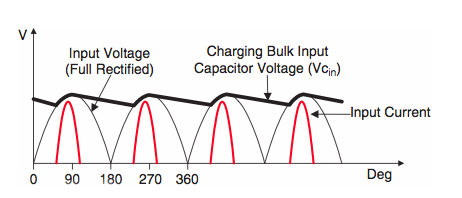
By comparison to magnetic HMI ballasts, electronic HMI ballasts are quite a bit more complicated. In an electronic HMI ballast, AC power is first converted into DC. Then, a high-speed switching device (micro processor controlled IGBTs) turns the flat current into an alternating square wave. Hence, they are commonly referred to as square wave ballasts. Electronic square wave ballasts utilize solid state electronic components which use only portions of the input power sine wave. Put simply, they place all their load on the peak values of the power waveform. These devices then return the unused portions to the power stream as harmonic currents.

As illustrated above, these harmonic currents stack on top of one another creating harmonic distortion that likewise creates an opposition to the flow of current, pulls the voltage and current out of phase, and when the power is supplied by a generator can lead to severe distortion of the voltage waveform in the power distribution system.

Left: Conventional generator power w/ pkg. of non-PFC Elec. HMI Ballasts & Kino Flo Wall-o-Lite. Right: Inverter generator power w/ Pkg. of PFC Elec. Ballasts & Kino Flo Parabeam 400.
For example, the power waveform above left (from my article) is typical of what results from the operation of a 2500W non-Power Factor Corrected load (electronic HMI & Kino ballasts) on a conventional portable generator (a Honda EX5500 with a Barber Coleman Governor.) The severe harmonic noise exhibited here can cause overheating and failing equipment, efficiency losses, circuit breaker trips, excessive current on the neutral return, and instability of the generator's voltage and frequency. The opposition to the flow of current caused by harmonic distortion is called capacitive reactance. Where I am about out of space I will pick up with how Power Factor Correction in electronic square wave ballasts work in a subsequent post.
Guy Holt, Gaffer, ScreenLight & Grip, Boston