Robert Hart
Well-known member
- Joined
- Feb 26, 2012
- Messages
- 1,258
- Reaction score
- 3
- Points
- 38
For those brave few Red One owners who risked the ire of the RED's parent and fitted the P+S Technik IMS-Mount to their cameras, this might be of interest if you are operating the camera in windowed 2K or HD mode for higher frame rates but want to retain some of the 35mm field-of-view and shallower depths of field more consistent with 35mm lenses. I will attempt to post the images but I may exceed a permitted ration. We shall see how that turns out.
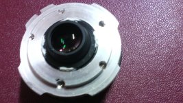
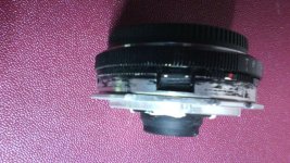
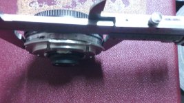
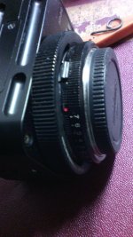
Here are a few rough images of the modified Speedbooster with IMS adaptor attached.
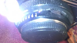
You will observe four white patches of adhesive around the optical cell at the rear. I had to use this because the original lock screw remains on the M4/3 adaptor which the IMS adaptor replaces. The lock screw on the original M4/3 adaptor is not good design because it forces the optical cell to rest slightly off-axis in the Speedbooster body because the sloppy fit of the threaded section.
I understand that this defect has been fixed in later Speedbooster builds by using a threaded collar on the rear of the optical cell to lock it squarely in place once the backfocus has been correctly set. I have not yet enquired with Metabones if that lock ring is available as a separate part.
This whiter material is water-cleanable white bathroom sealer. I use it because it can be picked away with a needle or sharp knife point if I make an error. Do not put it on the threads. Just use it as a tack across the joint. Do NOT use clear silicon. If it gets on the glass, it is impossible to clean off without damaging the lens coating.
For setting backfocus ( collimating the optical cell in the Speedbooster ) ,I position the camera facing directly down towards a test chart with my best known good lens with accurate focus marks pointed at the chart at a measured distance from the focal plane to the chart. I adjust the optical cell until the focus is correct. I do this by removing the lens and turning the optical cell from the front, the remounting the Nikon lens.
The reason why I face it straight down is so that the optical cell rests square to the optical axis due to gravity pulling on the threads along the optical axis. If you try to set the focus of the cell horizontally, it may tilt off-axis because the thread clearance is sloppy.
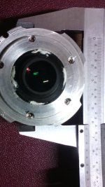
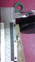
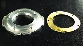
You will observe the cut-down rear of the Speedbooster. The vernier caliper shows the diameter which just allows the lugs of the IMS-Mount clamp ring to clear the Speedbooster body. Your IMS-Mount clamp ring may be of the lighter style used on the old Mini35-400 adaptor. In that instance, you will not have to remove as much as the 6mm forward of the rear of the Speedbooster body as I have. That 6mm you see on the vernier includes the 0.2mm brass shim which cannot be seen in the image.
In this modification, you lose the little lens support but if you make a curved spacer, you can remount the support if you revert the Speedbooster to its M4/3 mount.
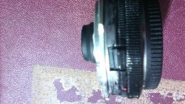
The lug on the IMS-Mount clamp ring turns a little past the original position I had arranged because of wear on the metal I have used, aluminium plate from Austal Ships factory scrap bin. I hope you can see the amount of material I filed off the little release slider which pulls the locking pin back iknside the Nikon mount to release the lens. This must be filed down to allow the IMS-Mount lock ring lug to barely pass over without catching .
Be careful not to file too much plastic off the slide handle because it is molded around a thin metal structure and will split away if too much material is taken.
You must dismantle the Speedbooster body and clean out the grease so that metal filings do not stick inside. Be careful not to lose the little ball-bearings inside of the aperture ring. They are an absolute dog to put back in afterwards when re-assembling the Speedbooster.
I hope this is helpful. Good luck with it. I post this with strong recommendation that you do yhour own independent research to verify what I have suggested here. - You proceed entirely at your own responsibility. As the man says in Rambo 3, "If anything happen to you, I am not responsible".
Here are a few rough images of the modified Speedbooster with IMS adaptor attached.
You will observe four white patches of adhesive around the optical cell at the rear. I had to use this because the original lock screw remains on the M4/3 adaptor which the IMS adaptor replaces. The lock screw on the original M4/3 adaptor is not good design because it forces the optical cell to rest slightly off-axis in the Speedbooster body because the sloppy fit of the threaded section.
I understand that this defect has been fixed in later Speedbooster builds by using a threaded collar on the rear of the optical cell to lock it squarely in place once the backfocus has been correctly set. I have not yet enquired with Metabones if that lock ring is available as a separate part.
This whiter material is water-cleanable white bathroom sealer. I use it because it can be picked away with a needle or sharp knife point if I make an error. Do not put it on the threads. Just use it as a tack across the joint. Do NOT use clear silicon. If it gets on the glass, it is impossible to clean off without damaging the lens coating.
For setting backfocus ( collimating the optical cell in the Speedbooster ) ,I position the camera facing directly down towards a test chart with my best known good lens with accurate focus marks pointed at the chart at a measured distance from the focal plane to the chart. I adjust the optical cell until the focus is correct. I do this by removing the lens and turning the optical cell from the front, the remounting the Nikon lens.
The reason why I face it straight down is so that the optical cell rests square to the optical axis due to gravity pulling on the threads along the optical axis. If you try to set the focus of the cell horizontally, it may tilt off-axis because the thread clearance is sloppy.
You will observe the cut-down rear of the Speedbooster. The vernier caliper shows the diameter which just allows the lugs of the IMS-Mount clamp ring to clear the Speedbooster body. Your IMS-Mount clamp ring may be of the lighter style used on the old Mini35-400 adaptor. In that instance, you will not have to remove as much as the 6mm forward of the rear of the Speedbooster body as I have. That 6mm you see on the vernier includes the 0.2mm brass shim which cannot be seen in the image.
In this modification, you lose the little lens support but if you make a curved spacer, you can remount the support if you revert the Speedbooster to its M4/3 mount.
The lug on the IMS-Mount clamp ring turns a little past the original position I had arranged because of wear on the metal I have used, aluminium plate from Austal Ships factory scrap bin. I hope you can see the amount of material I filed off the little release slider which pulls the locking pin back iknside the Nikon mount to release the lens. This must be filed down to allow the IMS-Mount lock ring lug to barely pass over without catching .
Be careful not to file too much plastic off the slide handle because it is molded around a thin metal structure and will split away if too much material is taken.
You must dismantle the Speedbooster body and clean out the grease so that metal filings do not stick inside. Be careful not to lose the little ball-bearings inside of the aperture ring. They are an absolute dog to put back in afterwards when re-assembling the Speedbooster.
I hope this is helpful. Good luck with it. I post this with strong recommendation that you do yhour own independent research to verify what I have suggested here. - You proceed entirely at your own responsibility. As the man says in Rambo 3, "If anything happen to you, I am not responsible".