Welcome to our community

Be a part of something great, join today!

  • Hey all, just changed over the backend after 15 years I figured time to give it a bit of an update, its probably gonna be a bit weird for most of you and i am sure there is a few bugs to work out but it should kinda work the same as before... hopefully :)

Cutting through the hype surrounding Light Emitting Plasma (LEP) lamps

Hey guy,

I sure don't mean to be reckless but have a discussion and thought sharing about LEP technology.
You keep pointing on the projector versions but I am pointing out to the ENT version.
Witch is build for use for theater, stage and film spots, as the manufacture is pointing out !!
Were trying to get more specs about it.

Most here are profs, freelance or business owners.
So I don't think people here are putting a projector light into a film spot and aspect it works fine.

If I have the time, I'll try to contact Luxim about the ENT version.

 
I called Luxim today to ask about the ENT 31 and STA 40 Emitters as theres some doubt. The Luxim PDF's are clear in that universal orientation is supported for both, Luxim say they are checking and say they will confirm but it may be the 40 may not be universal as the PDF states. I will post here what I find out.
 
I really like these CINESOFTS … Using true tungsten and Daylight Diodes …..

You have to be wary of all the claims made by head manufacturers. Whenever a new lighting technology comes on the market, the manufacturers put a little spin on the scientific data which has a tendency to cloud issues. For instance, if you compare the spectral power distribution graphs of LEDs below to that of a Tungsten source you can see that there is no such thing as a true “Tungsten” LED diode (the same is true of Daylight LED Diodes – see my newsletter article for details.)

LED_Comp_Sprectrum.jpg

A spectral power distribution of a lamp indicates how much energy is present in each part of the spectrum. As you can see above, Tungsten lamps have a continuous spectrum. Given how they produce white light, even high CRI Phosphor White LEDS have a discontinuous spectral quality that is unlike that of Tungsten lights. In the case of the 3200K Phosphor White LEDs above, the phosphors added shape the spectral distribution by enhancing certain colors in the spectrum to simulate the spectral distribution of incandescent light. As a result, the spectral distribution of Phosphor White LEDs resembles a series of peaks and valleys. There is a big spike at about 465nm (the blue LED) and a broader bump between 500 and 700nm produced by the phosphors. Even though the spectral power distribution has these peaks and valleys, the human eye perceives the light as white light.

While the discontinuous spectral distribution of high CRI Phosphor White LEDS may appear white to the eye, and the color of objects illuminated by it appear natural to the eye, to film emulsions and digital imaging systems designed to reproduce accurate color under continuous spectrum light sources (like daylight or incandescent lamps), the color of the same objects will appear unnatural on screen (as the illustrations below make clear.) That is, the hue of an object being illuminated by this "white light" can be drastically different than expected when it appears on the screen. For example, below is a "Macbeth chart" contrasting the resulting effect upon different color swatches of studio tungsten light and a representative high CRI Phosphor White LED lighting instrument.

LED_Macbeth_Tungsten-WhPhos.jpg

Split Macbeth chart: each color patch shows the visible effects of studio tungsten light in the top half of the patch, and a representative Phosphor White LED lighting instrument in the bottom half. ​

A common test chart used for assessing color performance of motion picture imaging systems, the chart above would be more accurately called a "split Macbeth chart" because each color patch shows the visible effects of the two light sources; studio tungsten in the top half of the patch, and the Phosphor White LED instrument in the bottom half. Although your computer display is not likely to be a calibrated reference monitor, the wide variations in color patch hue caused by the discontinuous spectral distribution of the Phosphor White LED should be readily apparent.

What accounts for these results? First, as you can see from its' spectral power distribution above, Phosphor White LEDS, compared to continuous light sources, have no output at wavelengths shorter than about 425nm, which means that violet colors don't render well. Second, there is minimal output in the medium blue-cyan-turquoise range from about 465-510nm, which is why the aqua-type colors don't render well either. Lacking these complementary colors within the spectrum, skin tones and warm, amber-yellow colors don't stand out. Third, with the long-wavelengths cutoff in the high-600 nm range, pinks, reds, oranges, and other long wave-length colors tend to look a little dull under Phosphor White LEDs, compared with how they look under continuous spectrum light sources (daylight, HMI, Tungsten) which extend all the way out on the long-wavelength end. Finally, as you can see from the gray scale at the bottom, this particular Phosphor White LED Luminary has an overall magenta bias. While you can white balance out/time out this magenta bias in digital video cameras/digital film intermediate, the camera/timer is not able to replace the parts of the spectrum that are missing all together. And since gels only rebalance the spectral distribution of a light source by passing the wavelength of the color that they are, gels cannot correct for these deficiencies because there is not much light of those wavelengths to pass in Phosphor White LEDs to begin with.

LED_Model_Comp.jpg

Left: Tungsten source, Right: White Phosphor LED source.​

This inability of Phosphor White LEDs to render color accurately is very visible in tests recently performed by The Academy of Motion Picture Arts and Sciences (AMPAS) as part of their “Solid State Lighting Project Technical Assessment.” (see http://www.screenlightandgrip.com/html/emailnewsletter_generators.html#anchorHigh Output AC LEDs for details.) In one (above) a model was photographed wearing a dress that had a number of different blue tints. Footage was shot with both a true tungsten source and a White Phosphor LED source. The tungsten-lit footage displayed all of the subtle differences in blue tones in the fabric, while the LED-lit footage, lacking cyan output, showed just a nice blue dress, without the same richness of hue. You can also see above that, absent cyan, the skin tones don’t stand out because that complementary color (cyan) within the spectrum is not present. Since the light doesn’t put out much cyan, the camera/film simply can’t record it. And, as Cinematographer Daryn Okada, ASC, discovered the hard way, color gel packs, camera white balance, or digital intermediate timing can’t bring it out if it isn’t there to begin with.

Like many of us, Daryn Okada uses LEDs as “touch up” lights to add a little something where key lights don’t cover. Needing to touch up a face on one talent mark, he once hid a small LED unit behind a chair, to add some glow to an actress’s face when she reached a mark where the keys had fallen off. “The manufacturer claimed the unit to be a ‘tungsten LED source’” he recounts. “She stopped right in the doorway, where I had this LED, and looked fine. But when I got the dailies back, her face was totally magenta.”; What’s worse, Okada says the image could not be repaired in post, because there wasn’t enough of the right color of light in the scanned negative for a color timer to bring out. This is a good example of the fact that, the bottom line is that, simply by nature of their discontinuous spectral distribution, even high CRI Phosphor White LEDs will never accurately reproduce colors on screen regardless what can be done in post. To make matters worse, common color meters, like the Minolta III F, are completely useless with LEDs in determining what gels to use. The meter makes its calculation of the color temperature based on an assumption that the light source has a continuous spectrum. Color readings of an LED have been shown to be misleading for both correlated color temperature and green/magenta shift. And, manufacturer’s CRI ratings are not necessarily the best indicator to judge the color rendering capability of LED fixtures because it is a measurement that can be messaged by manufacturers to give high readings without giving good results.

I really like these CINESOFTS ….. you can change the color temperature to like 2600 to 6500k using the on board dimmer.

The idea that you can achieve a nominally correct CCT for any color temperature from tungsten to daylight using only two sets of LEDs is also a bunch of marketing hype. While it intuitively makes sense that you can achieve an intermediate color balance by balancing the output of “Tungsten” and “Daylight” LED diodes, this approach does entail a compromise non-the-less.

LED_Blenders.jpg

If on the chromaticity diagram above, you were to plot the color point of two illuminants, all the colors that are possible by mixing the two colors of light will be located on the straight red line drawn between the two points. However, the line (black line above) that would be charted by heating a black body radiator (as it turns red, orange, yellow, white, and finally blue as it is heated) is not a straight line, so it is not possible to create light that remains neutral in terms of their green/magenta shift, while mixing only the two colors.

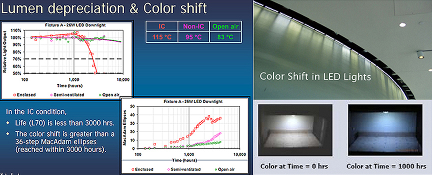
Another drawback to White Phosphor LEDs that broadcast studios lit exclusively with them are finding out is that, as illustrated below, their output depreciates overtime and their color shifts much faster than the manufacturers say.

LED_Lumen-Color_Shift_A.jpg

As I said at the outset, you have to be wary of all the claims made by head manufacturers. Whenever a new lighting technology comes on the market, the manufacturers put a little spin on the scientific data which has a tendency to cloud issues. For this reason, to pick the right LED luminary for a particular job it helps to have a thorough understanding of the technology. For our company newsletter I have put together an overview of the technology and what LED products are available for motion picture lighting (available at http://www.screenlightandgrip.com/html/emailnewsletter_generators.html#anchorHigh Output AC LEDs.)

Guy Holt, Gaffer, ScreenLight & Grip, Lighting Rental and Sales in Boston.
 
I called Luxim today to ask about the ENT 31 and STA 40 Emitters as theres some doubt. The Luxim PDF's are clear in that universal orientation is supported for both, Luxim say they are checking and say they will confirm but it may be the 40 may not be universal as the PDF states. I will post here what I find out.

Dave I am looking forward what your finding out.
Maybe Luxim has a demo/sample kit around the LIFI-ENT-31-02.
 
A question I've had rolling around in my head is: given that the plasma is excited by a large dose of RF focused on the bulb, are there consequences in terms of interference with audio systems running in close proximity to the heads? Anyone have any info on that?
 
A question I've had rolling around in my head is: given that the plasma is excited by a large dose of RF focused on the bulb, are there consequences in terms of interference with audio systems running in close proximity to the heads? Anyone have any info on that?

There is not much information yet as manufacture specs leave more questions then answers.
The best way is to measure, or someone that has a demo kit could do it (and the right environment to test) .

As guy pointed out before, and also to me being reckless for discussing and thought sharing about the LEP's.
He has a real point about health and safety, and it is of course wise to check regulations (ISO, CE. or what is local needed)
bevore taking it to any production etc.
It is good that Guy has pointed out this subject, I assume his generator modifications pass all the regulations needed to be operating on set.

The best way is to measure the RF, UV (a & b) and IR in the right environment, and see how much shielding or blocking is needed to operate the LEP in a safe way.
The wave frequencies the emitter is producing seem to be at the same as wireless mics use.
So testing would in a safe environment the best option.
 
A question I've had rolling around in my head is: given that the plasma is excited by a large dose of RF focused on the bulb, are there consequences in terms of interference with audio systems running in close proximity to the heads? Anyone have any info on that?

We have equipment to check this here. We only have a development kit not a manufacturers fixture but we can test next week and post here.
 
There is not much information yet as manufacture specs leave more questions then answers.… it is of course wise to check regulations (ISO, CE. or what is local needed)before taking it to any production etc… The best way is to measure the RF, UV (a & b) and IR in the right environment, and see how much shielding or blocking is needed to operate the LEP in a safe way. The wave frequencies the emitter is producing seem to be at the same as wireless mics use. So testing would in a safe environment the best option.

The RF drivers that power plasma emitters run at 900MHz, so the emitter housings have to be specifically designed to contain the RF. As Robert Rutherford, the other co-creator of the Hive lights explains: “It’s like a microwave… keep the door shut and everything works fine. Unfortunately, this does mean that you can’t just put a plasma emitter in any old head. Without our proper shielding, the RF energy, even though it’s less than 0.1 milli-watts, can do some very funny things to wireless mics and walkie talkies.”

With proper shielding in the housing design it is possible to block the RF from interfering with radio mikes. Lamps similar to these have been used in event/stage/tour lighting applications for a number of years (see samples below.) You can be certain that they do not cause RF interference if they are being used in event/stage/tour lighting applications.

Plasma_Theatrical_Hds.jpg

As you can see there are a lot of design considerations that go into building a LEP lamp for motion picture applications. As far as I can tell, the head manufacturers of LEP lamps for motion picture lighting applications have been able to address the issues of lamp orientation, UV emissions, and RF interference within the framework of a light that makes practical sense for motion picture production because they can manufacture custom components (given the benefits of manufacturing economies of scale) not available to the average user.

Guy Holt, Gaffer, ScreenLight & Grip, Lighting Rental & Sales in Boston
 
As guy pointed out before, and also to me being reckless for discussing and thought sharing about the LEP's. He has a real point about health and safety, and it is of course wise to check regulations (ISO, CE. or what is local needed) before taking it to any production etc. It is good that Guy has pointed out this subject, I assume his generator modifications pass all the regulations needed to be operating on set.

We have in fact designed our HD Plug & Play Pkg. Gen-set to meet and exceed OSHA requirements (most portable generators do not) and operate safely in wet environments. To assure safe distribution of power from the generator in the wettest conditions, our 60A Full Power Transformer/Distro uses an Epoxy Encapsulated Core with a "3R" all weather rated housing. With the transformer windings, core, and lead connections sealed in epoxy inside a tough, waterproof casing, our 60A Full Power Transformer/Distro will withstand the harshest outdoor conditions - making them the clear choice for power distribution from portable generators on wet locations.

SB_Gen-Trans_PS_Sm.jpg

A 100 GFCI with our 60A Transformer/Distro meets OSHA requirements
for use of a Honda EU6500is generator on work sites.
​

Since, moisture can also cause ground faults that can endanger the lives of those working on wet sets, many municipal electrical codes and OSHA require the use of Ground Fault Circuit Interrupters (GFCIs) in wet conditions. Even though, ground fault protection can eliminate electrical hazards and save lives, many productions shoot without GFCIs because they are prone to tripping when used with Kino and HMI ballasts, or are simply not available on the super quiet generators (the Honda EU6500is for instance does not have GFCIs.) They are also not commonly available for 120V branch circuits larger than 20 Amps. To eliminate the problems associated with the use of common GFCIs on portable genertors, we bond the Neutral to the ground in our 60A Full Power Transformer/Distros so that a 100A Shock Block (a GFCI specifically designed for use with motion picture lights) can be used to provide GFCI protection for lights up to 6kw. In fact, our 60A Full Power Transformer/Distro is the only way to bring the Honda EU6500is generator into full OSHA compliance (it does not meet OSHA requirements for use on work sties otherwise) by enabling the use of a 100A GFCI (use this link for for more details.)


SB_Location_Still.jpg

A single 100A GFCI "Shock Block" can provide ground fault protection on wet locations for the entire distro system of a Honda 6500 portable generator when used in-line with a Step-Down Transformer/Distro. ​


Designed for underwater, outdoor, and wet-location filming, a 100A GFCI Shock Block provides UL943 Class "A" protection. Featuring a 6mA trip level, it will assure protection for people and equipment from ground faults. Unlike standard home GFCIs, it uses an "Inverse Time Curve" to prevent nuisance tripping by electronic Kino & HMI ballasts that can cause costly production delays. And, to deal with the harmonics that non-PFC Kino & HMI ballasts kick back into the power stream (that will cause other GFCIs to trip), a 100A GFCI Shock Block includes a harmonic filter with a frequency response up to 120 hz. 3rd harmonics are attenuated by 50%, and by 500 Hz are down to 20%. Attenuated by the filter, the harmonics generated by dirty loads such as non-PFC Kino & HMI ballasts, pose less of a problem. Finally, to assure your piece of mind, it includes a test function that enables you to confirm it works. Adapted with 60A Bates connectors, it is easy to install in-line after our 60A Full Power Transformer/Distro and will provide safe and secure ground fault interruption for an entire distribution system consisting of Bates Extensions, Bates Splitters, and Bates-to-Edison break out boxes - eliminating the need for finicky Hardware Store style GFCIs.

Used in-line with our 60A Full Power Transformer/Distro, a 100A GFCI Shock Block also provides a larger GFCI protected circuit than is available on any other portable generator (by comparison the largest GFCI circuit available on a Honda EB6500 is only 30Amps.) In fact, it enables the operation of even 4k HMIs with GFCI protection. Specifically tailored to the type and size loads used in motion picture production, a 100A GFCI Shock Block, when used on our modified Honda EU6500is with our 60A Full Power Transformer/Distro, provides reliable ground fault protection for larger lights, or more smaller lights, than has ever been possible on a portable gas generator. Our system meets and exceeds OSHA requirements for the use of portable generators on work sites ( click here for a detailed explanation of OSHA requirements and how only our HD P&P Pkg. meets them with the Honda EU6500is.)

For more detailed information on using shock blocks to provide ground fault protection with portable Honda generators, I would suggest you read the article I wrote for our company newsletter on the use of portable generators in motion picture lighting.

BoxBookLinkGenSetSm.jpg

This article is cited in the just released 4th Edition of Harry Box's "Set Lighting Technician's Handbook" and featured on the companion website "Box Book Extras." Of the article Harry Box exclaims:

"Great work!... this is the kind of thing I think very few technician's ever get to see, and as a result many people have absolutely no idea why things stop working."

"Following the prescriptions contained in this article enables the operation of bigger lights, or more smaller lights, on portable generators than has ever been possible before."​

The article is available online at http://www.screenlightandgrip.com/html/emailnewsletter_generators.html.

Guy Holt, Gaffer, ScreenLight & Grip, Lightng & Grip Rental in Boston
 
OK, so I called Luxim today to clarify our own proposed use for their products which I must add look excellent in our view.

Im told both the LIFI ENT 31 and LIFI STA 40 series are good for Universal orientation i.e. can point up as well as down, so if the other considerations are met orientation should not be a issue. It is the LIFI- STA 40-02 version for the 'projector kit' sold by a third party mentioned in this thread.

As others have mentioned there are many other factors to consider too but for both these types it seems they are built for any orientation so satisfactory for our types of use.

Thank you very much for sharing! This clears much confusion on this subject.
It seem that Luxim LIFI ENT 31 and STA 40 are perfect for our use.

I'll try to find out more about RF blocking, and post it as i find out more
 
Last edited:
@ Guy

I love the work you do, educate and inform us with lot of your knowledge (harmonize-, loop-, interferences issues, and created a solution that meets production needs)
I think lot of us (and i of course speak only for my self) want a clearer understanding, testing and experiment with LEP's.

There is great potential for cinema and photography use.
And personal I love the smart design of Hive and it is clear there has been a lot of thought and development in there products.
They shouldn't be scared of us but listen and see with ideas we come up with, it will create more potential for there product development.

For of market parts, it depends a lot where you life, here in EU there is really a lot to get on a B2B level.
 
I also ran the STA 40-02 for a couple of hours vertically, horizontally and down. It ran fine no problems.
 
I also ran the STA 40-02 for a couple of hours vertically, horizontally and down. It ran fine no problems.

That is great to hear!

What i find out in short notice.
As with the RF pointed out as 0.1 mili-Watt, it is very very low.

To put in perspective:

- A regular cellphone produce about 2watt RF or 2000 mili-Watt
- A wifi signal produce about 0.1watt or 100 mili-watt

A real life measurement should be a better way.
I'll try to find the shielding materials but does any one know how much heat there is produced (not inside the bulb) but in a closure?
Because there are quite a lot of paint materials with RF blockers that can cut a lot of RF in dB's but paint introduce different issues.

As i can find for now (don't pin me on to it it's late here, please correct if i am wrong) there is a 10 dB shielding needed to cut 0.1 mili-watt RF
 
http://www.instrumentplastics.co.uk/product.php?p=17

There are some plastic products here but the glass would be much better, also mesh is is used for screening.

One point that is made is this thing gets hot so any gasket materials can off gas if very hot causing a layer of coating on the glass which makes it unusable so best ask for the design guide for some guidance on issues and likely problems.
 
@ Dave,

info I found out:

As you stated before, underwater lighting would be the main purpose.
The RF issue is different as water slow down (absorbing) the frequencies and natural damping the RF.

0.1 mW RF doesn't cause healthy issues and is only a interference issue with wireless communication devises and mics by emitting on the same wave length.
Proper grounding will be essential for RF shielding, or no material will work for good shielding.
Choosing the right materials of making the housing and good grounding, should lower RF radiation (aluminum, stainless steel, copper etc.) .
For heat resistant shielding I only could find copper or nickel plated Kapton from DuPont but it is not very practical.
I'll search for some paint with all the required characteristics (if i can find it).

Edit:

I filled in the contact page of Luxim about more information and the Demo kit, I'll wait there reply.
 
Last edited:
I can only report the kit we have is working fine. No problems in any burning position. Light quality is very nice from whats virtually point source.
 
Unfortunately the diyprojectorkits LEP is no longer available from them. I was going to get one to experiment with, but they took it off their store and told me they weren't carrying them anymore. Bummer. Now I guess the way to get them is to go to Luxim directly and order one of their development kits, which I think runs around $1000.
 
Back
Top